de en

KS FREQUENCY CONVERTER

FOR COMPLEX TESTING

Clever system solutions for engine and powertrain testing.

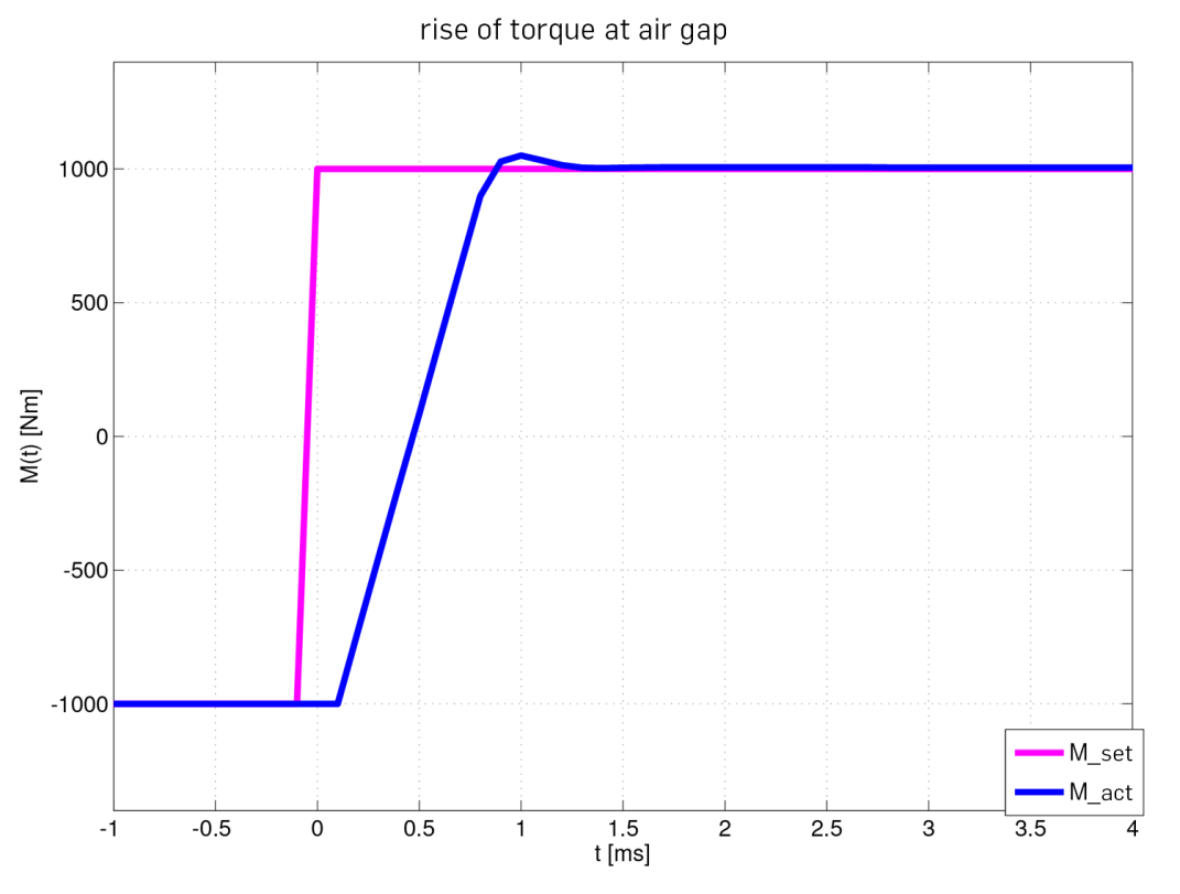
The KS R2R frequency converter is an integral part of the high-performance testing technology KS supplies for complex testing requirements. The use of cutting-edge semiconductor modules in combination with faster signal processing and holistic, model-based control engineering facilitates highly dynamic applications. The best possible control performance is achieved using mathematical models of the test bed as well as the latest control algorithms. This system solution is the key to results that have never been seen before in engine and powertrain testing.

Advantages

• 1700 A continuous current – 2800 A or more with parallel units
• Output frequency of up to 2000 Hz
• Internal clock rate of up to 20 kHz
• Switching frequency of up to 10 kHz
• Time-based torque measurement, 250 MHz
• Water-cooled inverter modules
• Highly dynamic torque control
• Inertia compensation across a broad range
• Fast EtherCAT interface
• DC link voltage:
  600 V for nominal voltage of 400 V
  1000 V for 690 V

CONTROLLER MODES

• Controller mode “M” (classic)
• Controller mode “Mplus” (inertia compensation, R2R, haptic test, ...)
• Controller mode “n” (classic)
• Controller mode “nplus” (super stiff speed control)
• Virtual additional damping

EXAMPLE OF INERTIA COMPENSATION

CONTROLLER MODE M

CONTROLLER MODE M

FUNCTION

• Torque setpoint Mset as well as limits Mmax and Mmin can be preset
• Field-oriented control attempts to implement MLS=Mset as well as possible, but will never achieve total accuracy (model error)
• In most cases, a superimposed controller is required to regulate the shaft torque.

ADVANTAGES

• Compatible with classic torque control

CONTROLLER MODE MPLUS

CONTROLLER MODE MPLUS

FUNCTION

• Mset and the measured torque Mmeas are used together with the desired inertia JR to calculate a speed setpoint nset (principle of angular momentum)
• For the user, this acts as a torque control


ADVANTAGES

• In the steady state, Mmeas = -Mset exactly!
• Inertia compensation and cogging torque reduction – The specimen does not “feel” the full rotor inertia!
• R2R (Mset from the tyre model), haptic test (Mset = 0)
• Torque limits nmax, nmin can be preset

CONTROLLER MODE N

CONTROLLER MODE N

FUNCTION

• Torque setpoint nset as well as limits Mmax and Mmin can be preset (transfer control!)
•  The control performance depends on the PI parameters and can be selected between “soft” and “hard”
•  The controller only reacts to a difference between nset and nact, i.e. there is a deviation for a shaft torque jump

ADVANTAGES

• Compatible with classic speed control

CONTROLLER MODE NPLUS

CONTROLLER MODE NPLUS

FUNCTION

• In addition to the normal speed control, the measured shaft torque is superimposed inversely
• For a constant speed setpoint nset, the PI controller would ideally be superfluous (torque sum equals zero)
• For a shaft torque jump there is almost no deviation

ADVANTAGES

• Especially good (“super hard”) speed control
• Shaft resonance frequencies can be damped

VIRTUAL ADDITIONAL DAMPING

FUNCTION

• With MVZD (applied as an additional air gap torque), the shaft behaves for the electric machine as with a damping dW + dV
• An estimate of Δω with the help of Mmeas (Kalman filter) is required

ADVANTAGES

• Increases the damping of the shaft virtually
• Has a shaft-resonance-damping effect for resonant frequencies up to approx. 50 Hz
• Can be switched on and off infinitely variably in all controller modes

Advantages

TORQUE INCREASE IN THE AIR GAP

While conventional industrial converters have considerable delay times in the transfer of the setpoint and increase of the torque at the shaft, these are significantly reduced in the KS FC and a setpoint jump at the EtherCAT interface is implemented immediately as a shaft torque by means of extremely fast signal processing. The rapid setpoint transfer and the direct control of the IGBTs make the KS FC an ideal element in highly dynamic control circuits.

The combination of KS frequency converter technology, with its model-based control engineering and a holistic approach to testing and test bed components, forms the foundation for the dynamics and precision the KS high-performance testing technology delivers. Our multidisciplinary test bed engineers optimise the test bed configuration with respect to specific testing requirements and circumstances.

Example


PMSM: Pn = 800 kW (overload 1600 kW)
Procedure: steep speed ramps

Advantage:  

• Motor speed ramp 50,000 rpm/s
• Generator speed ramp 50,000 rpm/s


POSSIBLE APPLICATIONS

EXAMPLES OF CONTROL PERFORMANCE

EXAMPLE OF TORQUE FLUCTUATIONS / SIDE SHAFTS


Initial situation: specimen with 8-cylinder ICE

Test procedure: Steady-state load operation

Special aspect: Torque jolts from the ICE are evident in the measured values of the axle torques and can be allocated to individual cylinders.

EXAMPLE OF ABS BRAKING ON SNOW-COVERED ROADS


Initial situation::

• Vehicle is driving on a level snow-covered road with µ-low
• Speed is 50 km/h

Test procedure:

• Emergency braking manoeuvre initiated
• Full braking with ABS intervention

Special aspect: ABS intervention works in exactly the same way as on the road