de en

FUEL CELL-STACK TESTING

PRECISE AND DYNAMIC AT THE SAME TIME

Tailor-made test benches for fuel cell short stacks. Reproducible Testing in the developmente stage.

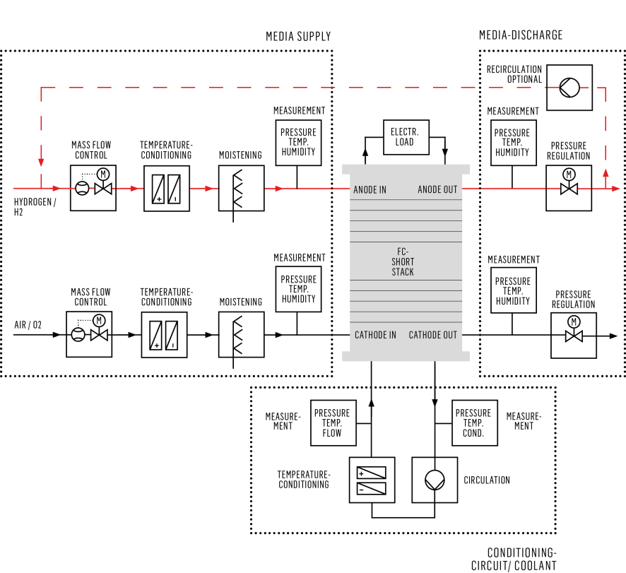
Highly efficient fuel cell systems play an essential role with regard to future drive concepts. The reproducible testing of complete fuel cell systems as well as the examination of individual stacks and BoP components play a decisive role in development. With tailor-made test benches for fuel cell short stacks, KS offers the necessary flexibility to deal with a wide variety of scenarios and test tasks. The system configuration is adapted to the specific application with regard to the required operating ranges as well as the required accuracy and dynamics

TEST SCENARIOS

  • Function tests
  • Reliability studies
  • Long-term tests
  • Characterisation of cell components

  • Optimisation of operating parameters
  • Map determination
  • Design optimisation
  • End- of- Line tests

FEATURES

  • Stack preconditioning
  • Hydrogen recirculation
  • Automatic regeneration of the cooling circuit
  • Automatic filling & emptying of the cooling circuit

For the operation of a short stack on the test bench, air and hydrogen are provided as the media supply and an electronic load (sink) as the consumer. In addition to power and current, the manipulated variable can also be the stack voltage. The parameters of hydrogen, air and cooling medium required for operation are precisely and highly dynamically regulated.


The control concept for this is configurable. State-of-the-art security technology guarantees unattended 24/7 operation. The basis for this is the development of a comprehensive safety concept consisting, for example, of the safety-related consideration of the test item and test sequence, Ex Zone classification, design of the necessary safety devices and the development of on-site precautions.

WORKING PRINCIPLE

MAIN COMPONENTS

TEST CHAMBER:

• Convenient positioning of the test specimen, Visible from all sides
• Access protection to the test specimen via door contact switches
• Integrated extraction hood with hydrogen sensors ensures constant extraction of the test area during normal operation and controlled extraction when hydrogen is released.

ANODE PATH:

• Temperature, humidity, pressure and mass flow control of the anode path (hydrogen path)
• Anode exhaust gas recirculation

AIR CONDITIONING:

• Cathode supply air: The fuel cell/stack is connected and sealed to the process air path and supplied with conditioned compressed air (temperature, humidity, pressure and mass flow).

COOLING CIRCUIT / STACK COOLING:

• Separate cooling circuits depending on requirements
• Accurate pressure, temperature & flow control

NITROGEN PATH:

• Flushing the anode path (hydrogen path)
• Flushing the stack cooling circuit
• Supply of the hydrogen valves

ELECTRONIC DC-LOAD:

• 19“ slide-in module integrated in the automation system
• Voltage, current & power ranges depending on customer requirements

DYNAMIC CONTROL:

• High demands on the pressure control in the anode and cathode circuit is achieved through the use of model-based control technology in conjunction with highly dynamic control flaps.